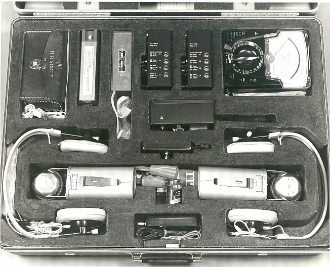
This kit, circa 1968, had no nomenclature other than the "CM Kit." It was affectionately know as the "2 hern" because it weighed 85 pounds which would give you a double hernia if you tried to lift it. The handles didn't help much either. The kit centered around my products... 2050CA RF locator, two 1019 audio amplifiers (predecessor to the 1059), 2030 carrier current probe, 2040 test oscillator. Also included were a Triplett meter, HH Scott UV source with charger, two 50K headsets and two flashlights. All of this was in the bottom layer of the kit.
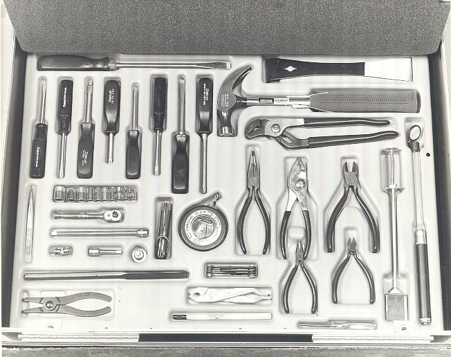
These hand tools were in the center layer of the kit.
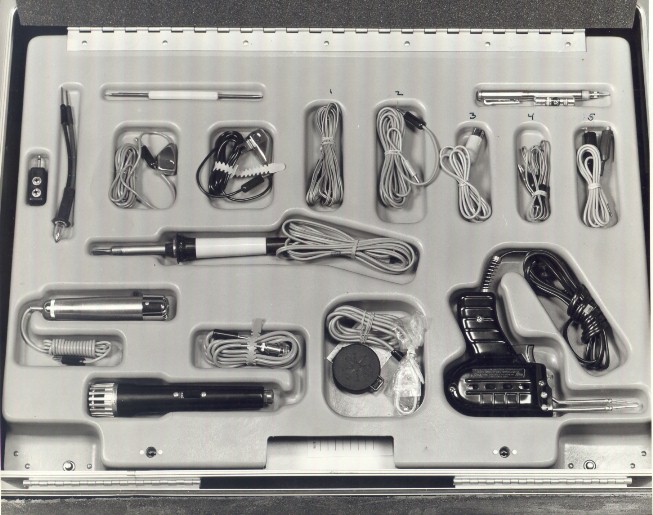
The upper layer of the kit contained these tools.
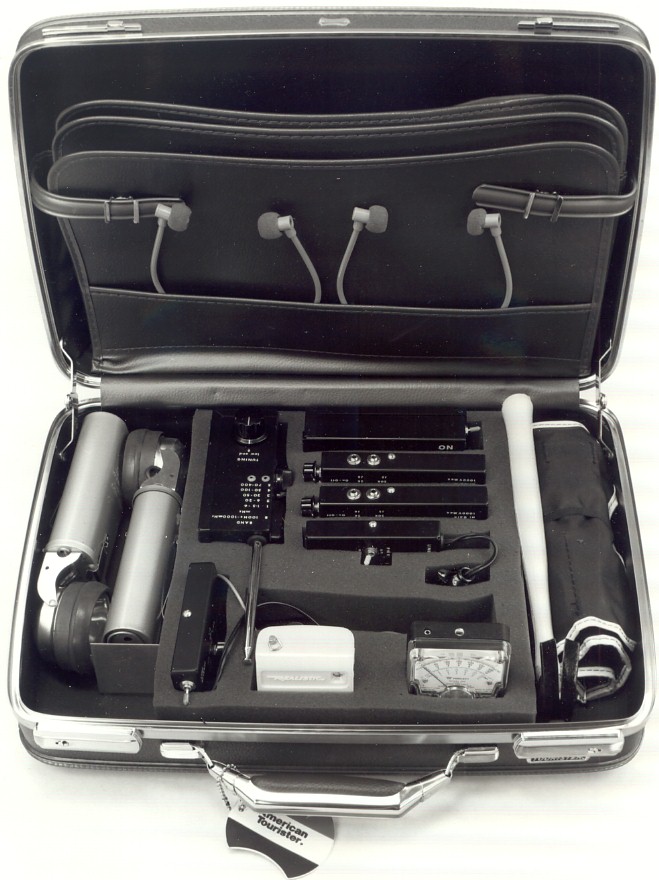
The 1040 countermeasure kit, circa 1969. This kit contained my 2050CA RF locator, two 1059 preamps (they replaced the 1019s in the original CM kit), 2030 carrier current detector, 2040 test oscillator, an Excelite tool kit to replace all of the individual tools in the CM kit, 1040-4B 270 volt hot-pack, a smaller meter, two headsets, two flashlights and an AM/FM radio for a known noise source.
The 1040 series Countermeasure Kits contain all the tools necessary to physically disassemble a room (sweep area), check it for surreptitious listening devices and put it back together. Included in the kit are radio frequency (RF) detectors for locating transmitters and carrier-current devices, audio frequency (AF) amplifiers for tracing and locating wired devices, an optical probe for infrared (IR) devices and an assortment of test equipment, cables and accessories and tools.
The 1040 kit contained two (2) 1059 general purpose audio amplifiers, two (2) special high impedance 1059H headsets, a 2050CA RF transmitter locator, a 2030 Carrier-Current detector, a 2040B RF Test Oscillator and a 1040-4 Hot Pack for testing and hi-potting AC and telephone lines, a general purpose test meter, a variety of test leads and adapters, two (2) adjustable focus flashlights and assorted mechanical and electrical hand tools.
Instruction sheets on each of the major components will be found later in this manual.
The 1059 audio amplifier has multiple input/output impedances to provide a good match for most microphones, lines and recorders. It is specifically designed to drive the special 2,000 ohm 1059H headset supplied. A tone generator is included for testing amplifier performance and unknown line pairs. A two position high pass-low pass filter switch helps eliminate unwanted signals and a switch able excitation voltage is available for supplying power to external accessories. The 1059H headset can be used with the ear hook and adjusted for either ear. When used with the gray stethoscope tube, the tube is worn under the chin with the sound output holes facing slightly forward (30 degrees). The stethoscope tube is the preferred method.
The 2050CA RF locator is a sensitive hand-held relative field strength indicator with visual, tonal and aural readouts. It is not designed to replace a sensitive countermeasure receiver or spectrum analyzer. A six (6) position BAND switch selects either a broadband detector or one of five tunable frequency bands. An RF signal intercepted by the antenna is amplified to drive the meter and/or HEADPHONES jack. A separate circuit produces a tone with pitch proportional to signal strength. with the AUDIO/TONE switch on TONE the unit functions much like the well known "Geiger" counter. with the switch on AUDIO the audible component of the transmission can, under many conditions, be monitored through the headset.
The 2030 carrier current detector detects devices that use the AC power or telephone lines to transmit a signal.
The 2040B provides operational field checks on the 2050CA and 2030 probe. The unit operates on an internal 9 volt battery supply and not ll0 VAC. Make sure to turn it OFF when not in use.
The 1040-4 Hot-Pack is included as an aid in testing for devices which do not conduct current until after an initial "breakdown" voltage is applied. The unit contains a battery powered high voltage generator and current limiting circuit.
The most important aspect of ANY countermeasure survey (sweep)is knowing what to look for and where to look for it. There is no way this manual or countermeasure kit can provide that primary function. The purpose of the 1040 kit is to assist the technician accomplish an effective sweep.
PLANNING: Two approaches to the sweep may be taken; one alerting (where the opposition knows the sweep is in progress), the other non-alerting (where the opposition is kept from knowing the sweep is in progress). The following procedures should be adjusted as required for each sweep.
Make sure all equipment is operable and in place in the 1040 Kit. On entering the suspect area, the first step is to draw a simple floor plan. This information is of invaluable assistance when later describing the suspect area to others.
PHYSICAL SEARCH: The next step is to perform as thorough a physical search as possible. Remove all cover plates from power sockets, light switches and telephone jacks. Remove the mounting screws of the sockets and switches and pull them out as far as the wires permit. USE EXTREME CAUTION WHEN WORKING WITH HOT AC POWER LINES!! Use the flashlight to visually inspect the inside of every socket and switch housing. Use the handle end of the insulated fuse puller to push the wires to assure they are rigid. Flexible and/or soft wire may indicate a shielded or coaxial cable leading to a microphone or circuit. If such a cable is located, mark its location for future evaluation. Microphones hidden within the housing need no further explanation. There are, however, microphones connected to small diameter tubing (tube microphones) that can be mounted outside the housing and the tube fed inside. Look carefully for any small tube extending into the housing. After all the sockets and switches have been visually inspected, test them for normal voltages. Use the multi meter which has been set on the appropriate range check for AC voltages. Again, EXERCISE CAUTION. Measure the voltage across the sockets; it should be 110 volts. If a socket shows no voltage make sure it is not the result of a switch not being turned on. The following test should be performed if there is no logical reason why voltage is not present.
Plug the 1059H headset into J6 and the mini-plug to clip cable into J1 if the 1059. with one hand inserted in a rear pocket and held as a clenched fist (this makes sure that an inadvertent shock does not pass through vital areas of the body), use the other hand to connect the BLACK clip (shield) to the side of the socket with the WHITE (neutral) wire. Connect the RED clip to the other side (BLACK - hot wire). Advance the VOLUME control one quarter of a turn clockwise. Slowly turn the J1 GAIN control clockwise while listening for room sounds. If a loud hum is heard, it is probably AC so CAREFULLY, AGAIN, USING ONE HAND ONLY, disconnect the clips. If, when J1 GAIN reaches full range, room noise is recovered, it is safe to assume that a microphone is concealed in the socket. Replace the sockets, switches and covers at this time. Test all sockets and telephone lines with the 2030. Remember, there are two sockets per outlet, check both. Use the 1059 to locate and trace any speaker wires to their destination and source. This includes the speaker in the speaker-phone portion of the telephone.
Where possible, inspect all air ducts by removing the grill plates. Lift any drop ceiling tiles and inspect. The flashlight and hand held mirror are useful at this point. A step ladder comes in handy too. Slightly lift floor and corner molding to check for hidden wires. Visually inspect the underside of drawers, desks, chairs, tables or any other piece of movable furniture for suspect devices. An 8010G metal detector (optional) could be helpful here. Set the multi meter the R X 1K position and test all unplugged AC appliances. Incandescent lamps should be turned on and then unplugged (before the bulb gets too hot). Remove the bulb but leave the appliance turned ON. without touching the metal portions of the multi meter probes or lamp plug measure the resistance across the power cord. It should be infinite. After touching the plug for a few seconds to make the measurement, quickly reverse the two test leads while carefully watching the meter for capacitive "kick". The meter should not budge.
Clocks, fluorescent lamps, certain types of "instant on" TV sets will show a relatively low resistance at all times. These appliances will require visual inspection of the interior. Unplug them before inspecting! Bear in mind that most power leads are of the two wire type. If a power lead is discovered which has three or more wires, inspect very carefully. Most chairs within a room are moved on too frequent a basis and normally do not provide a good location for direct wired microphones. Desks, however, remain in the same spot over great periods of time. Move any desks slightly to look for wires. If the desk is too heavy to move, raise each leg one at a time and slide a credit card underneath it to push out any wires. Do a complete physical inspection of every object in the room. Use common sense. This completes the physical search. Follow the instructions for the 2050CA and 2030 to locate RF sources.
TELEPHONE TESTS: The telephone represents a genuine threat simply because it contains too many microphones to leave unattended in a room. The mouthpiece, ear piece speaker portion of the speaker-phone all are effective microphones. Anyone who ever leaves a telephone in a secure area should be questioned as to their intent!! Do not take the threats inherent with this instrument too lightly. Thanks to the breakup of A T & T there is now a proliferation of telephones and telephone systems far too many to describe in individual detail. A common thread usually runs throughout any telephone system. The first is that all the telephones in any particular system are like peas in a pod. The insides of one telephone will look just like another. For this reason it is best to have on hand a spare telephone that can be placed besides the one being inspected for comparison. Look carefully for add-on circuits or evidence of tampering with the circuit boards i.e. jumpers, external components, etc. Make a log which contains as much detail as possible about each telephone and keep it for future reference.
Once a thorough physical inspection is made, proceed with the electronic testing. Pick up the telephone handset and punch up the first line (if there is more than one line). Again, point the probe at the front, top, back and both sides of the telephone while listening for the dial tone or room audio. Do the same on all remaining lines. Prepare the 2050CA for normal operation. Place the unit on BAND 3 and the white line on the TUNING control pointing directly away from the words LOW END. with the telephone hung up, pass the antenna over the telephone while listening for the presence of RF. Do the same on bands 4 and 5. pick up the telephone handset and punch up the first line (if there is more than one line). Pass the 2050CA antenna over the telephone and handset on bands 3,4 and 5. Do the same on all remaining lines. Most telephone systems are either 4, 6, 8, 25 or 50 wire type. A 1080E is helpful, but not necessary, when checking 4, 6 and 8 wire systems. With the telephone hung up, use the 1059 to listen to every possible pair combination for room audio. Then use the 2030. While still using the 2030, punch up the first line and listen for recovered audio. Test the remaining lines in the same fashion. Next, use the multi meter measure the voltage, both DC and AC, on every pair combination. Log this information. Checking another telephone in the same system should produce the same results. By far, the best way to perform the above tests using the 1059 and 2050CA is to use the "feedback" technique. Run the mini-plug to mini- plug cable from J6 of the 1059 or the 2050CA HEADPHONES jack to the audio jack located on the rear of the modified AM/FM radio. Adjust the volume so an audible hiss can be heard and place it next to the telephone instrument. Proceed with tests while listening for feedback howl.
The following instruction sheets give operating details for the key parts of the 1040 Kit. In time, all of these parts will blend into effective results.
1059 PREAMPLIFIER: The 1059 is designed as a multiple input/output low noise amplifier that can provide a near perfect match to just about any microphone or recorder. The 1059 includes a tone generator for testing am amplifier performance unknown lines, switch able excitation voltage for external accessories and a low pass/high pass filter selector. The input jacks, J1 through J4, provide input impedances from 2 Megohms down to 1,000 ohms. Maximum amplification is provided through J2 and J3 and medium gain through J4. J1 and its associated J1 GAIN control has adjustable amplification. with the J1 GAIN control advanced fully clockwise the output level of a signal fed into J1 will be roughly one-half that of the same signal fed into J2. J1 can sustain approximately 1,000 volts DC. This jack should be used when it is uncertain as to how much voltage or type of signal is on an unknown line pair. To operate the 1059, insert the 2,000 ohm headset supplied into output jack J6. The headset is worn with the gray tube under the chin with the sound output holes facing slightly forward. The 1059 is NOT designed to drive low impedance headphones. Turn J1 GAIN fully counterclockwise (minimum) and advance the VOLUME control clockwise (turning on the amplifier) roughly one-third turn. Advance the J1 GAIN control slowly clockwise until either a signal is recovered or the control reaches full clockwise. If, while advancing J1 GAIN, a loud hum is heard, it probably indicates that the line is carrying high voltage AC. USE CAUTION! Do not apply high level AC signals to any other input.
J2 (500K) is a high impedance input which utilizes the maximum amplification of the 1059. This jack is used when the DC and AC level and relative signal strength on a line pair is known. J2 may also be used with external accessories such as the 1040-2 Contact Microphone and 1040-4 Hot-Pack.
J3 is used when the line or accessory is in the vicinity of 10K ohms. This jack is used with accessories such as the 2030 Carrier-Current Probe or when analyzing telephone systems. J4 provides lower amplification and impedance (1,000 ohms) than J2 of J3. It is used when an input signal is too high in level for the other inputs. This jack also has the capability of supplying an excitation voltage (9 volts through 4,700 ohms) for external accessories or carbon microphones. The voltage is supplied to the jack when the J4 VOLTS switch is in the UP position. The TONE-ON switch powers an internal tone generator. The output of the generator is fed through the last three stages of the amplifier and applied to both output jacks, J5 and J6. The FILTER-IN switch selects the amplifier roll-off characteristics. This switch is used when excessive hum is encountered or when a more "crisp" signal is desired. A convenient check of the battery can be made by inserting the mini plug-clip lead cable (supplied) into J4, turning ON the 1059 power and placing the J4 VOLTS switch in the UP position. Connect the clips to a voltmeter set on the 9 or 12 volt range. The voltage should indicate not less than 8 volts for an alkaline battery or 7.5 volts for a mercury battery. Should it become necessary to change the battery, loosen the two cover screws one or two turns, slip off the cover and remove the old battery. Install fresh battery, replace cover and tighten screws (don't over-tighten!).
2050CA RF LOCATOR: The 2050CA is an ultra-sensitive hand-held radio frequency (RF) detector with visual and tonal readout of relative signal strength. The six position BAND switch selects either a broadband detector or one of five tunable ranges. The amplified signal is displayed on the meter, as a tone whose pitch is proportional to signal strength or as demodulated audio of signals with an amplitude modulated (AM) component. In the tone/pitch mode the unit functions much like the well known Geiger counter.
OPERATING INSTRUCTIONS: Connect the antenna to the BNC jack on the top of the unit. Extend two or three sections using only the heaviest or larger diameter sections. Insert the headset (Note: The 2050CA is designed for use with a high impedance headset such as the 2,000 ohm unit supplied). The headset is worn with the gray tube under the chin and the sound output holes facing slightly forward (30 degrees). Apply power by rotating the SENSITIVITY control clockwise to about three-quarters of its range. Set the TUNING control so the white indicating line is pointing directly away from the words LOW END. Start with the BAND Switch in position 1. Sweep an area (such as a wall) about 4 to 5 feet wide with the antenna vertical. Sweep the same area with the antenna horizontal and then perpendicular. Sweep the same area on bands 2 through 5. Move on to the next 4 to 5 foot area. After the walls, bookshelves, etc. have been swept, go over each and every piece of furniture, getting the antenna as close as possible. If the meter goes off scale or the tone abruptly stops or goes too high in pitch reduce the sensitivity by rotating the SENSITIVITY control counterclockwise to no less than the 9 o'clock position. If that is not sufficient, shorten the antenna one or two sections. When a strong signal is located it can, under some conditions (i.e. signals with an AM component), be monitored by switching the TONE/AUDIO switch to AUDIO.
The 2050CA will locate high power radio or TV stations up to several miles. The unit will also locate low power signals (1 to 10 milliwatts) at distances of 5 to 25 feet. When searching for low power transmitters bear in mind that high power signals can be reflected, re-directed and appear to reradiate from the least expected places. Therefore, use common sense when performing RF sweeps. If additional sensitivity is needed, rotate the TUNING control for maximum indication on the meter. The BAND Switch position B is for sweeps where broadband detector at lower sensitivity is desired. When the switch is on B, the white line on the TUNING control should be pointing directly away from the words LOW END. Newer versions of the 2050CA have an unmarked jack on the left side of the unit. This is for external accessories such as the 1 to 20 GHz extender antenna.
NOTES: The frequencies shown on the BAND Chart are approximate and used as reference points only. The unit should be stored or I shipped with the antenna disconnected, the BAND Switch in I position 5 and the TUNING control pointing towards the words LOW END. Alkaline batteries are preferred. Remove the battery if the unit is stored for prolonged periods of time.
2030 PROBE: The 2030 is designed to locate radio frequency (RF) transmitters or carrier-current devices using the AC or telephone line as their power source. Carrier-current devices are generally only effective on the secondary side of a power transformer but can travel considerable distances on telephone lines. The unit consists of an input cord/antenna, a LINE REVERSE switch, an RF-CARRIER switch and a BAND selector switch which selects one of six broadband circuits. The 2030 contains NO battery and must be used with an amplifier such as the 1059. The input cord will withstand a maximum sustained DC or 50/60 Hz AC level of 1,000 volts. This limit would, of course, include telephone ring voltages. The carrier signal is passed through the 1 line cord to the LINE-REVERSE switch where it can be electrically reversed. The RF-CARRIER switch either connects one side of the line to chassis common (CARRIER position) or allows it to float (RF position). The output signal contains demodulated audio Which is amplified by the external amplifier.
OPERATING INSTRUCTIONS Insert the 2030 output cable into the audio amplifier (such as J3 of the 1059). with the RF-CARRIER switch in the CARRIER position, insert the line cord into each and every outlet in the search area and listen to the detected signal in each of the six bands. Throw the LINE REVERSE switch to the opposite position and again listen in each of the six bands. Remember, there are two sockets per outlet; check both. Place the RF-CARRIER switch in the RF position and again check each and every socket in each of the six bands for detected signals. It is not necessary to use the LINE REVERSE switch when testing for RF. These same tests may be performed on a telephone line by using a pair of clip leads to connect the AC plug to the line. ALWAYS USE EXTREME CARE WHEN WORKING WITH AC POWER LINES!!
2040B TEST OSCILLATOR: The 2040B is designed to provide operational field checks for the 2030 Probe and 2050CA Detector. The 2040B, however, can be used as a signal source for testing many types of radio frequency (RF) countermeasure equipment. The unit consists of a self-excited tone modulated oscillator operating at five preset frequencies. The output signal can be obtained from either the collapsible antenna or line plug. The unit operates on its own internal 9 volt battery and not the AC line plug. Output at each of the five frequencies is determined by selection of the appropriate band. The RF output is approximately 5 milliwatts (mW). The frequencies shown on the front of the unit are approximate and merely show the group within which the carrier will appear.
TESTING THE 2030 PROBE: Adjust the 2030/1059 for standard operation in the 1-5 MHz band. Insert the line plug of both the 2030 and 2040B into adjacent AC power receptacles. Turn on the 2040B and set the band switch in the 5 MHz position. A tone will be heard from the 2030/1059 indicating proper functioning. If desired, test the operation of the 2030 on all other bands. TESTING THE 2050CA DETECTOR: Adjust the 2050CA for standard operation in the 1-5 MHz band. Extend the antenna on the 2040B and turn ON the power. Hold the antenna of the 2050CA approximately 4 inches from the antenna of the 2040B. DO NOT ALLOW THE ANTENNAS TO TOUCH! Adjust the TUNING control on the 2050CA for maximum indication. With the 2050CA adjusted for AUDIO the tone from the 2040B will be heard in the headset.
1040-4 HOT PACK: The 1040-4 is designed to serve as a high voltage, current limited source for testing telephones, intercoms or electrical appliances. The unit contains a single 240 Volt photoflash battery (Eveready 491). Battery output is applied f through a momentary ON/OFF switch and limiting resistor to the OUTPUT LEVEL control. The momentary ON/OFF switch serves both as a safety device, should inadvertent contact occur with the test leads, and battery saver. The negative side of the battery is tied directly to the BLACK - terminal while the positive output is delivered from the center contact of a 1 Megohm potentiometer. In operation, the RED + terminal may be varied from 0 to 240 Volts DC (no load condition). The voltage and current output of the 1040-4 is a direct function of the resistive load applied. OPERATION: Insert the black test lead into the BLACK - jack. Insert the positive (red) test lead of the multi meter into the RED + jack. Set the multi meter the 6 ma. range. Short the black test lead of the 1040-4 to the black test lead of the multi meter. Pull the ON switch upward and set the OUTPUT LEVEL for a reading of 5 ma. Release the ON switch. Separate the two black test leads. Now, whenever the switch is turned ON, 240 Volts will appear at the end of the two black leads. BE CAREFUL! While observing the meter, apply the test leads to all circuits which should be an open circuit, i.e. the hook swswitch contactsn a standard telephone or an electrical appliance which is turned off. Any indication of current will show that the unit may have been tampered with and requires further inspection, Always check in both polarities by reversing the two black test leads.
REPLACING THE BATTERY: Remove the two cover screws and place the unit lettered side down on a soft surface. Carefully remove the bottom cover. Lift the battery upward and outward. CAREFULLY remove the positive (red) lead first; then the negative (black). Reverse the procedure for inserting the new battery. Make sure the battery leads are positioned so the back cover will not pinch them when it is replaced.
NEW BATTERIES: Experience with the type of high voltage battery used in the 1040-4 has shown that occasionally a blemish may appear on the outer surface. This blemish, usually caused by an accidental drop of battery acid, will form an unexpected contact. This does not necessarily indicate that the battery is bad. Simply cover any blemishes with two layers of plastic electrical tape.
1040F FLASHLIGHT (LIGHT STICK) The "Light stick" is one of the most convenient flashlights made. The adjustable focus, flexible headpiece with spare bulb and belt clip stand out among its many features. The light is powered by four "D" cells which are installed two facing downward and two upward as indicated by the arrows stamped in the top edge of the case. Although expensive, Alkaline batteries are always preferred. The light uses a #27 bulb (5 V @ .3 A) and a spare bulb is located under the reflector. That bulb can be accessed by completely unscrewing and removing the reflector/focus ring. The light is turned on by the slide switch located under the headpiece. Point the light at a distant wall and adjust the focus by rotating the reflector/focus ring. The belt clip may be used for carrying or hands free viewing objects overhead. As with any piece of battery operated equipment, remove the batteries during periods of prolonged storage.
When not in use, keep the hand tools, mirror, fuse puller, test leads, pry bar and accessories in the storage pouch.
Back To Products Home © 2008-2009
3/09