DIFFERENTIAL R F PROBE
 The 2055HA detects low level radio frequency (RF) radiation from transmitters, receivers, computers, etc. One of the two antennas detects towards positive while the other detects towards negative, therefore, if the source of RF energy is away from the two antennas (i.e. 20 feet or more) both antennas receive essentially the same amount of energy and the meter remains at zero. As the ratio of the distance between the RF source and the antennas decreases, one antenna receives more RF than the other and the meter swings in that direction. This effect is known as near field or differential detection.
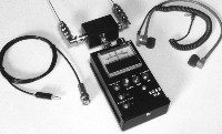
The 2055HA covers frequencies ranging from lower than 10,000 Hz (10 KHz) to over 1,000 MHz or 1 GHz. The system consists of: amplifier/indicator assembly, RF head assembly, head extension rods, head extension cable, two multi-section antennas, two right angle BNC connectors, special 2,000 Ohm headset, carrying case and instructions
TO OPERATE: Insert the RF head assembly into the BNC connector on the top of the amplifier/indicator assembly and position it so the pole mounting screw faces away from the operator. Connect the two antennas with right-angle adapters to the RF head and position so they are parallel. For frequencies from 10 KHz to 100 MHz use three antenna sections. For freguencies from 100 MHz to 350 MHz use two antenna sections. For frequencies from 350 MHz to 1 GHz use one section. For frequencies from 1 GHz to 4 GHZ use only the right angle adapters. For frequencies above 4 GHZ remove the adapters and use only the BNC connectors. Insert the headset supplied into the HEADSET-2K jack. Do NOT use a low impedance headset (it simply will not work). The clear plastic portion of the earbuds may be unscrewed for cleaning. Turn the unit ON and place the TONE/AUDIO switch in the TONE position. Zero the meter with the ZERO SET control at the top of the unit. Press the + BATTERY TEST button. The meter will swing to the right and a reading in excess of +.8 (+8V)indicates satisfactory battery condition. Pressing the - button causes the meter to swing to the left and again, a reading in excess of -.8 (-8V) indicates a satisfactory battery condition. Adjust the antennas as described above pass them over the test area. If a signal is located, the meter will swing in the direction of the source and pass through zero when the source is perpendicular to the two antennas. Since the tone heard through the headset has a pitch proportional to the meter reading, it is not necessary to observe the meter while searching for the source. The lowest pitch tone indicates zero and the tone increases in pitch on either side of zero. The RF head can be extended with the extension handles and cable. Plug the cable BNC connector into the BNC jack at the bottom of the RF head. Plug the mini-plug into the jack located to the left of the BNC plug on the amplifier/indicator assembly.
NOTE: The RF head is NOT a 50 ohm assembly. The antenna, right angle connector and the outer shell of the coaxial connector are all at antenna potential. This assures maximum detection above 500 MHz.
The 2055HA MK V may also be used as a single antenna RF detector by removing the left antenna and zeroing the unit. The meter will swing only to the right when a signal is located. If the meter goes beyond full scale to the right, the zero may be suppressed to the left of center as required. The TONE/AUDIO switch causes either a tone proportional to the meter reading (TONE) or demodulated AM audio (AUDIO) and some FM (by slope detection) to occur at the headset. The DC output of the opamp is accessible through the RECORDER jack. This output drives a strip chart recorder. There is a spare set of diodes inside the RF head assembly. Should it become necessary to change the diodes, make sure the bands on the diodes face the YELLOW end of the diode holder.
Should either battery become weak (i.e. below .8), replace both batteries by removing the top and bottom screws from the amplifier/indicator assembly and carefully lifting off the back cover. Alkaline or Lithium batteries are ALWAYS preferred. While the back cover is off, note the three screwdriver adjust potentiometers. The one in the upper center above the upper integrated circuit is the rough zero. The control to the right (as viewed from the back) of the integrated circuit is the gain control. The control below and slightly to the right of the gain control is the base tone adjustment. To re-center the position of the ZERO SET control, set that control to mid-range and adjust the rough zero control for zero indication on the meter. To adjust the base tone, turn the ZERO SET control so the meter reads full scale (1.0) on either side of zero and adjust this control for a tone output of roughly 2 to 3 KHz.
GLOSSARY:
Hz - Hertz = one complete cycle per second
KHz - Kilohertz = 1,000 Hertz (Hz)
MHz - Megahertz = 1,000 KHz
GHz - Gigahertz = 1,000 MHz
THE 2055 HA MK V CONSISTS OF:
1 2055HA AMPLIFIER
1 RF DETECTOR HEAD
2 BNC RIGHT ANGLE CONNECTORS
2 MULTISECTION COLLAPSABLE ANTENNAS
1 DETECTOR HEAD EXTENSION CABLE
1 3 SECTION HEAD EXTENDER ROD
1 HEADSET
1 OPERATION INSTRUCTIONS
1 CARRYING CASE
6/12