1080TDR
TIME DOMAIN REFLECTOMETER
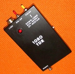 Designed for use with any oscilloscope with a band width in excess of 20MHz, the TDR supplies the necessary pulses to drive a wire pair to detect mismatchs or discontinuities. The unit has sufficient output to drive over two miles of wire.
 The 1080TDR, when used with an external oscilloscope, analyzes wire pairs... telephone lines, AC power lines, speaker wires, etc. The TDR is essentially an echo ranging device. It generates a short, very fast rise time pulse that travels along the wire pair at a speed determined by the velocity factor of the wire. When a mismatch or discontinuity is encountered, the pulse is reflected back along the wire pair to the oscilloscope. The actual distance to the discontinuity can be measured by simple calculation (keep a calculator handy). Use one of the input cables to connect the 1080TDR to the line under test. Connect the oscilloscope to the SCOPE connector. Set the vertical sensitivity to 5 volts per division or 0.5 volts per division if using a divide by ten probe (some oscilloscopes make this adjustment automatically) and the horizontal sweep at .1 microseconds (uSec) per division. Three different pulse lengths are generated; .1 uSec (SHORT) for lines up to 2,500 feet, .2 uSec (MEDIUM) for lines up to 10,000 feet and .5 uSec (LONG) for lines up to 10,000 feet. Set the TDR on LONG pulse. Sync the scope. The 15 volt pulse should be positive going. Set the horizontal position so the leading edge of the pulse is at the left-hand edge of the calibration marks on the screen. The rise time of the pulse is very fast and difficult to see. Increase the intensity if required. Set the vertical position so the trace rides on the center line of the screen. Connect a known length of telephone line or zip cord to the clip lead input cable (use a 100 foot roll of telephone or speaker wire usually available at your local radio store). With the TDR PULSE switch on S and the scope horizontal sweep set at .1uSec per division and the far end of the test line open circuited the following positive going pulse appears. 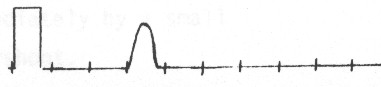
If the far end is short circuited the following negative going pulse appears. 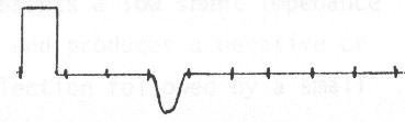 Measure the distance in microseconds to where the reflected pulse BEGINS TO LEAVE THE BASE LINE of the sweep. For 100 feet of wire with a velocity factor of .67 the pulse should occur at roughly .3uSec. Use the formula...
Therefore, 1000 X .67 X .3 DIVIDED BY 2 = 100 FEET.
The divide by two is necessary because it compensates for the fact that the pulse has to travel to the discontinuity and back.
When making TDR measurements bear in mind that the length of the pulse itself can mask the very near measurements. The .1uSec pulse will mask the first 35 feet of cable, the .2uSec pulse will mask the first 70 feet and the .5uSec pulse 170 feet (this is called a dead zone).
Increase the vertical sensitivity as necessary to compensate for loss of signal and to observe greater detail on longer lines.
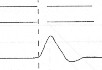
Here are a few signatures of the return signal...
Helpful hint. If the line under test is terminated by a telephone set or linemans handset place an audible beeper by the telephone handset or linemans handset. The reflected pulse, as seen on the oscilloscope, will pulse up and down at the rate of the beeper.
Formulas: TIME always in uSeconds. Vf = Velocity Factor
Unknown Length (L) = 1000 x VF x TIME
Unknown Velocity (VF) = (2 X LENGTH)/1000 x TIME
Unknown TIME = (2 X LENGTH)/1000 x VF The TDR has an output impedance of approximately 450 ohms. Initial reflected pulses arriving back at the analyzer/oscilloscope will again be reflected, travel back down the line to be reflected by the fault thus causing a second or "ghost" reflection at twice the fault distance. Watch for ghost reflections.
Multiple faults may or may not be observed. If the first fault encountered is severe, most or all of the pulse energy will be reflected thereby disguising other possible faults. After clearing the first indicated fault, go on to the second.
Telephone cables by nature of their construction produce displays that
are not "clean", i.e. free from bumps.
Velocity Factors (VF) can vary from .5 to .8. If the VF is unknown,
start with .67.
Back To Products Home © 2008-2009 1/09 |
 SHORTED CONDUCTOR The reflection from a shorted pair is a negative or downward pulse at the point of the short. There will be no reflection from the far end of the cable.
 SPLICES A splice produces a positive pulse followed
immediately
by a small negative overshoot.
SPLICES A splice produces a positive pulse followed
immediately
by a small negative overshoot.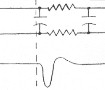 CAPACITOR BUILD-OUT NETWORK A network presents a low shunt impedance to the pulse and produces a negative
or downward reflection followed
by a small positive overshoot.
CAPACITOR BUILD-OUT NETWORK A network presents a low shunt impedance to the pulse and produces a negative
or downward reflection followed
by a small positive overshoot.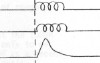 LOAD COIL A load coil presents a high series impedance to the
pulse and a positive or upward reflection. It is not possible to
see beyond the first load coil.
LOAD COIL A load coil presents a high series impedance to the
pulse and a positive or upward reflection. It is not possible to
see beyond the first load coil.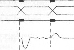 CROSSED OR SPLIT PAIRS The splice at which the split occurs is
indicated by a negative reflection. The re split is indicated by
a pulse of opposite polarity, but of smaller amplitude. First locate
and clear the split, then the re split.
CROSSED OR SPLIT PAIRS The splice at which the split occurs is
indicated by a negative reflection. The re split is indicated by
a pulse of opposite polarity, but of smaller amplitude. First locate
and clear the split, then the re split.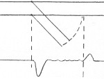 BRIDGE TAP The tap appears as a negative pulse followed immediately
by a slight positive overshoot. Because of multiple reflections
in this test, it is difficult to trace circuits that contain several
taps. Test progressively by moving from tap to tap.
BRIDGE TAP The tap appears as a negative pulse followed immediately
by a slight positive overshoot. Because of multiple reflections
in this test, it is difficult to trace circuits that contain several
taps. Test progressively by moving from tap to tap.