Push button to see
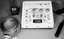
picture of 1080H MKII
|
Remove the 1080H MKII and charger from the carrying case. The charger operates from 110/240 50/60 Hz. Plug the output cable of the charger into the jack on the BACK of the unit. Plug the charger into the wall outlet. The RED Light Emitting Diode (LED) FAST CHARGE light on the charger and the CHARGING LED on the front will light, indicating charging is taking place. To observe the battery voltage, rotate the VOLUME control slightly clockwise until the unit turns on. The meter will read 00.0 volts. Disregard the + or - sign. Press the RED button below the words BATTERY TEST. The meter will read the battery voltage. Charge the battery when it drops below 12.0 volts. A reading of up to 13.8 volts is acceptable. Once the battery voltage is read, turn OFF the unit by rotating the VOLUME control fully counterclockwise.
The front panel may look confusing at first glance but the switch functions break down into several basic tests. The following is a description of each control. LINE PAIR: The two rotary switches in the upper right corner of the front panel provide every possible pair combination of the IN/OUT jacks located in the upper right corner of the analyzer case. These two jacks are wired in parallel i.e. 1 to 1, 2 to 2, etc. The lettered positions are for measuring line balance between tip (T) (4) and ring (R) (5) and earth ground. BALANCE C AND D: These push-button switches are used in conjunction with the LINE PAIR switch when measuring balance to earth ground. MODE: This switch selects the main function of the analyzer. The AUDIO position monitors audio on any line pair. CARRIER selects the carrier current receiver to monitor any carrier signals which might occur on any line pair. TONE generates four swept audio tones which cover all possible DTMF frequencies or any combinations which occur from 200 to 4,000 HZ. TDR (Time Domain Reflectometer) generates an extremely fast rise time pulse at 12 volts P-P for measuring line length (an external oscilloscope is required for this test). Three pulse widths at .1 uSec (S=SHORT), .5 uSec (M=MEDIUM) and 1.0 uSec (L=LONG) are generated. The OPTICAL (IR) position switches to the infrared (IR) PROBE that detects either basic amplitude modulated (AM) or frequency (FM) and pulse modulated IR-LEDs. IR PRIMARY/CARRIER: With the IR probe plugged into the IR PROBE jack, the MODE selector in the OPTICAL position and the IR switch in PRIMARY the probe monitors any AM IR activity in the vicinity of the analyzer. With the switch in CARRIER the carrier current receiver is switched into the circuit to detect FM and pulse IR signals. The carrier current receiver consists of three controls: CARRIER 10-100/100-700 KHz, TUNING LO-HI and GAIN (zero through MAX). The POWER/TONE indicator (LED) glows RED when the power is turned on and changes to GREEN when making a tone sweep of an active telephone line. The AUTO TONE SWEEP switch starts this process. The operation of this switch is explained later. The LOOP CURRENT push-button switch places a 100 ohm resistor across the pair selected by the LINE PAIR switches. The meter reads the voltage across this resistor, therefore, to convert the meter reading to amps, move the decimal point two positions to the left. The DC/AC METER spring-return switch converts the meter from DC to AC. The spring-return RESISTANCE switch measures the DC resistance across a pair selected by the LINE PAIR switches. A reading of 00.0 indicates infinite resistance while a reading between 199.5 and over-range (1 . ) indicates zero ohms. The internal speaker is disable whenever a headset if plugged into the HEADSET jack. The BNC connector on the back of the unit connects to an oscilloscope. This jack is common to the position of the two LINE PAIR switches. The BLACK binding post on the rear panel is for earth ground ONLY! This post is usually run to the ground pin (NOT the neutral) of an AC power outlet. The DIN jack adjacent to the BNC jack is for the 1080H-TDR external TDR for dual line comparison. The two 8 pin sockets on the upper right corner are, as mentioned before, wired pin for pin. Either one can be used for input or output. The 6 pin socket in the upper left corner is wired to the MIDDLE six pins of the 8 pin socket. Therefore, pin 1 of the 6 pin socket will occur at position 2 of the LINE PAIR. Pin 6 of the 6 pin socket will occur at position 7. This assures that the middle two wires of any cable are always the RED and GREEN wires. OPERATION: For initial startup set the controls as follows:
Remove the telephone plug from the wall jack and insert it into the appropriate jack. Use either the 6 or 8 wire pin-for-pin jumper cable supplied and connect it between the wall socket and the analyzer. Insert the headset. Turn the volume control clockwise to 9 o'clock. If the telephone has an eight wire cable start with the LINE PAIR in 1,2. If the telephone has a 6 wire cable start with the LINE PAIR in position 2,3. Make a list or chart of the readings. Note any voltage and listen for room audio. If the voltage is not steady and fluctuates widely, then it may be AC instead of DC. Pull the DC/AC METER spring-return switch forward and note the AC voltage. Then check and note 1,3; 1,4; 1,5; 1,6; etc. until all possible pair combinations have been recorded and listened to. Turn the MODE switch to CARRIER. Place the GAIN control at 12 o'clock and the CARRIER switch at 10-100 KHz. Return the line pair switches to 1,2. With the volume turned up so an audible hiss can be heard, rotate the TUNING control from LO to HI. Throw the CARRIER switch to 100-700 KHz and rotate the TUNING from HI to LO. Repeat this procedure on all possible line pair combinations. If, when testing in the AUDIO or CARRIER positions of the MODE switch, the voltmeter indicates zero volts (00.0) then measure the resistance of that combination. See the page on how to measure resistance later in this manual. If an active telephone line is detected i.e. a voltmeter reading of 48-52 volts was obtained in one of the switch positions, return to that position and run a tone sweep. Set the MODE switch on TONE. With the AUTO SWEEP switch in the down position the POWER/TONE LED is RED. Push the switch upwards for a second and return it to the down position. The POWER/TONE light turns GREEN and remains GREEN for the duration of the sweep. Allow the sweep to run for 2 to 3 minutes so the tone sweep can go through several cycles. If, during the sweep, a device is detected, the light will turn from GREEN back to RED. Immediately switch to the AUDIO position and listen to the device. The only way to stop the tone sweep is to turn the MODE switch to either side of the TONE position.
TDR MODE:
Designed for use with any oscilloscope with a band width in excess of 20MHz, the analyzer supplies the necessary pulses to drive a wire pair to determine line mismatches. The unit has sufficient output to drive over two miles of wire.
The 1080H MKII, when used with an external oscilloscope, analyzes wire pairs or transmission lines. The TDR portion of the unit is essentially an echo ranging device. It generates a short, very fast rise time pulse that travels along the wire pair at a speed determined by the velocity factor of the wire. When a discontinuity is encountered, the pulse is reflected back along the wire pair to the analyzer and oscilloscope. The actual distance to this discontinuity can be measured by simple calculation (keep a calculator handy).
If the far end is short circuited the following negative going pulse
appears. 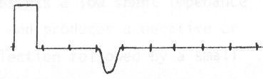 Measure the distance in microseconds to where the reflected pulse BEGINS TO LEAVE THE BASE LINE of the sweep. For 100 feet of wire with a velocity factor of .67 the pulse should occur at roughly .3uSec. Use the formula...
Therefore, 1000 X .67 X .3 DIVIDED BY 2 = 100 FEET.
The divide by two is necessary because it compensates for the fact that the pulse has to travel to the discontinuity and back.
When making TDR measurements bear in mind that the length of the pulse itself can mask the very near measurements. The .1uSec pulse will mask the first 35 feet of cable, the .2uSec pulse will mask the first 70 feet and the .5uSec pulse 170 feet (this is called a dead zone). This does not mean that measurements can not be made at lengths below 35 feet. To test short cables use the LONG pulse and make measurements on the TOP OF THE PULSE PEDESTAL itself. When doing this it will be necessary to adjust the vertical position so the top of the pulse is on the center line.
Increase the vertical sensitivity as necessary to compensate for loss of signal and to observe greater detail on longer lines.
Here are a few signatures of the return signal...
Helpful hint. If the line under test is terminated by a telephone set or linemans handset place an audible beeper by the telephone handset or linemans handset. The reflected pulse, as seen on the oscilloscope, will pulse up and down at the rate of the beeper.
Formulas: TIME always in uSeconds. Vf = Velocity Factor
Unknown Length (L) = 1000 x VF x TIME
Unknown Velocity (VF) = (2 X LENGTH)/1000 x TIME
Unknown TIME = (2 X LENGTH)/1000 x VF The TDR has an output impedance of approximately 450 ohms. Initial reflected pulses arriving back at the analyzer/oscilloscope will again be reflected, travel back down the line to be reflected by the fault thus causing a second or "ghost" reflection at twice the fault distance. Watch for ghost reflections. Multiple faults may or may not be observed. If the first fault encountered is severe, most or all of the pulse energy will be reflected thereby disguising other possible faults. After clearing the first indicated fault, go on to the second.
Telephone cables by nature of their construction produce displays that
are not "clean", i.e. free from bumps.
Velocity Factors (VF) can vary from .5 to .8. If the VF is unknown,
start with .67.
IR PROBE OPERATION: Plug the IR probe into the IR PROBE jack. Turn the MODE switch to OPTICAL (IR). Adjust the volume for a slight hiss. Place the IR PRIMARY/CARRIER switch in the PRIMARY position. Turn off any fluorescent lights in the area or shield the telephone being tested from direct fluorescent light. Pass the IR probe over the telephone while listening for room noise or conversation. The IR tests operate independently from the LINE PAIR selector and other tests. Next, place the IR switch in CARRIER. At a distance of six to eight inches, hold the probe steady over one portion of the phone and, with the GAIN control at 12 o'clock and the CARRIER switch on 10-100 KHz, rotate the TUNING control from LO to HI. Place the CARRIER switch in the 100-700 KHz position and rotate the TUNING control from HI to LO. Move the probe a few inches to the left/right or up/down and repeat these tests. Move the probe to the top, bottom and each side of the telephone and again repeat these tests. Repeat these tests as many times as necessary until the entire telephone has been viewed. The IR probe may be tested at any time with a TV remote control. When an active telephone line has been located in one of the LINE PAIR positions i.e. meter reads 48-52 volts, make a current test by pressing the LOOP CURRENT switch. Move the decimal point two positions to the left to obtain the actual current in amps (or one position to the right to read in milliamps). This test is only useful when testing 2 or more lines from the same exchange or switchgear. Test the battery voltage periodically. When it drops below 12.0, recharge it for a few hours. The headset is used for a variety of tests. It has long been held that the "feedback" technique produces more reliable results. To use the 1080H MKII in this mode place the headset ON THE TELEPHONE ITSELF. Turn up the VOLUME so an audible hiss can be heard a foot or so from the telephone. Run through all the tests previously outlined. If an audio path exists, a loud feedback squeal will be heard coming from the headset itself. MEASURING RESISTANCE: The internal calibration potentiometer (located on the
right side of the meter as viewed through the front panel) has
been preset at between 199.5 and over-range (1 . ) for zero ohms.
The ohmmeter circuit is powered by the 5 volt regulator that
supplies the meter. This regulator can drift a few millivolts
with temperature and this drift will affect the low resistance readings only. Below is a typical calibration chart for the ohmmeter.
|
|
|
| Turn the power on. The meter will read 00.0. Set the LINE PAIR switches on a dead short i.e. on the same number. Pull the RESISTANCE switch forward. The meter should read between 199.5 and over-range (1 . ). Release the switch. Set the LINE PAIR switches on the combination to be tested. Pull the RESISTANCE switch forward and note the meter reading. Using the chart above, convert this reading to an approximate resistance value. NOTE. A resistance reading can only be made on a line which has neither an AC nor DC component. MEASURING LINE BALANCE: The 1080H MKII can measure line balance with respect to earth ground. This test gives a rough indication of the resistance of the line and helps in detecting series devices. Turn on the analyzer. The meter will indicate 00.0 volts. Insert the 8 pin to clip lead test cable into either 8 pin jack. Only the RED and GREEN clips are used. Connect these clips to the line under test. Make sure any of the other clips do not touch the RED and GREEN clips. Connect an earth ground to the GREEN or BLACK terminal on the back of the unit. Earth ground can be accessed through the ground socket of an AC outlet. Do not use the neutral side. Set BOTH of the LINE PAIR switches on A. Note the voltage, including polarity. Set BOTH switches on B and note the voltage, including polarity. Set BOTH switches on C and press BALANCE switch C. Note the voltage. Set BOTH switches on D and press BALANCE switch D. Note the voltage. This last reading must be converted into current by dividing the reading obtained by 5,000. Note the D figure in AMPS. If the voltmeter fluctuates between tow numbers i.e. .2 and .3 then the voltage recorded should be .25. |
|
|
|
The final calculation will give the approximate line balance.
If the imbalance is from 50 to 250 a series device is indicated.
Disregard the final polarity.
One of the two readings for test A and B will be in the vicinity of 1 volt or less. If, for example, the other higher reading was negative in polarity then the smaller reading should be positive. If the higher and lower readings were both negative then a possible problem exists. A negative reading of more than .2 volts indicates parallel leakage. This could be water on the line so test another line pair in the same bundle. A reading of .5 or more negative could indicate a parallel device. If the higher reading obtained in the A and B test was positive then the converse would be true. EXAMPLE |
|
|
|
This result would dictate further inspection of the line.
DIGITAL TELEPHONES: Konexx (www.konexx.com) makes an excellent line of digital to analog (DAC) converters. Following is a list of some of their products that may be used with the 1080H MKII. As with any piece of electronic equipment, treat the 1080H MKII with care. Excessive heat or moisture can degrade its performance. If necessary, clean the unit periodically with a cotton or soft cloth lightly dampened with Windex or other window cleaner. |
1/09
 The rechargeable gelcell battery in the 1080H MKII is partially
charged prior to shipment. The first step is to fully charge
the battery. This can be done while proceeding through this manual.
The rechargeable gelcell battery in the 1080H MKII is partially
charged prior to shipment. The first step is to fully charge
the battery. This can be done while proceeding through this manual.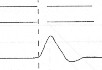
 SHORTED CONDUCTOR The reflection from a shorted pair is a negative or
downward pulse at the point of the short. There will be no reflection
from the far end of the cable.
SHORTED CONDUCTOR The reflection from a shorted pair is a negative or
downward pulse at the point of the short. There will be no reflection
from the far end of the cable. SPLICES A splice produces a positive pulse followed
immediately
by a small negative overshoot.
SPLICES A splice produces a positive pulse followed
immediately
by a small negative overshoot.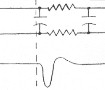 CAPACITOR BUILD-OUT NETWORK A network presents a low shunt impedance to the pulse and produces a negative
or downward reflection followed
by a small positive overshoot.
CAPACITOR BUILD-OUT NETWORK A network presents a low shunt impedance to the pulse and produces a negative
or downward reflection followed
by a small positive overshoot.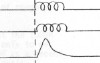 LOAD COIL A load coil presents a high series impedance to the
pulse and a positive or upward reflection. It is not possible to
see beyond the first load coil.
LOAD COIL A load coil presents a high series impedance to the
pulse and a positive or upward reflection. It is not possible to
see beyond the first load coil.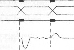 CROSSED OR SPLIT PAIRS The splice at which the split occurs is
indicated by a negative reflection. The re split is indicated by
a pulse of opposite polarity, but of smaller amplitude. First locate
and clear the split, then the re split.
CROSSED OR SPLIT PAIRS The splice at which the split occurs is
indicated by a negative reflection. The re split is indicated by
a pulse of opposite polarity, but of smaller amplitude. First locate
and clear the split, then the re split.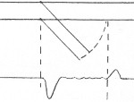 BRIDGE TAP The tap appears as a negative pulse followed immediately
by a slight positive overshoot. Because of multiple reflections
in this test, it is difficult to trace circuits that contain several
taps. Test progressively by moving from tap to tap.
BRIDGE TAP The tap appears as a negative pulse followed immediately
by a slight positive overshoot. Because of multiple reflections
in this test, it is difficult to trace circuits that contain several
taps. Test progressively by moving from tap to tap.