![]()
![]()
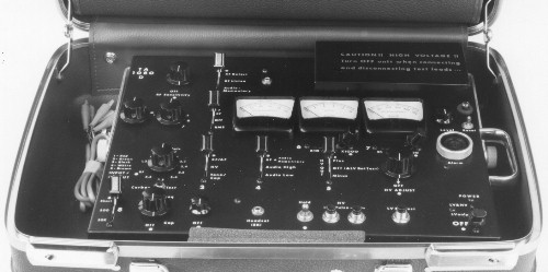
The 1080D is a completely self contained, battery operated analyzer designed to counter alterations to older U.S. and many foreign telephone and intercom systems. It measures voltage, current, capacitance, resistance, audio and radio frequency (RF) levels. The RF detector provides broadband detection from 50 KHZ to 10 MHZ and tunable detection from 10 to over 500 MHZ. An adjustable tone generator. A high voltage source varies from 0 to 1,000 volts and has an integral pulse generator. Meters measure various DC voltages, current, RF level and capacity. Two 9 volt batteries and two 500 volt photoflash batteries power the unit. The 1080D is supplied with input cable and headset and is housed in a standard size, attractive, quality attache case. Following is the original instruction manual... circa 1968.
I. GENERAL DESCRIPTION AND MAINTENANCE A. DESCRIPTION
A. RADIO FREQUENCY (RF) DETECTORS III. TELEPHONE TESTS
A. ON-LINE TESTSI. A. DESCRIPTION The 1080D Telephone Analyzer is designed counter modifications to telephone or intercom systems which would make them useful for eavesdropping while hung up or not in normal use. The unit incorporates RF detector, an audio amplifier, a tone generator, several metering circuits, a high voltage source pulse generators and a current sensing threshold alarm. Circuits within the analyzer requiring power are battery operated. B. BATTERIES AND REPLACEMENT PROCEDURE The low voltage (LV) supply consists of two (2) 9 volt transistor radio type batteries (alkaline preferred). The high voltage (HV) section is powered by two (2) 500 volt photoflash batteries (Eveready 497) wired in series to supply a DC output of 1,000 volts. The HV secti on is current limited and the HV output switch spring loaded to protect the operator from serious electrical shock if accidental contact is made with the output leads during test. Battery condition can be readily obtained by using the battery test Circuits. The following procedure is used should it become necessary to replace any of the batteries. TO AVOID AN ACCIDENTAL SHOCK, DO NOT TOUCH THE INTERNAL WIRING WHEN EXPOSED. ALWAYS TURN THE UNIT OFF AND DISCHARGE THE PULSE CAPACITORS WHEN REMOVING OR REPLACING THE HIGH VOLTAGE BATTERIES. ALWAYS WORK WITH ONE HAND ONLY AND WITH THE OTHER HAND INSERTED IN A REAR POCKET AND HELD IN A CLENCHED FIST.
1. Open the attache case fully.NOTE! The HV pulse capacitors will retain their charge for a considerable period of time. Carefully follow the instructions on how to discharge them.
a. Remove the bottom cover as outlined in I.B.4 and 5. NOTE. Experience with the type of HV batteries used has shown that occasionally a blemish may occur on the outer wrapping. The blemish, which may have been caused by an accidental drop of battery acid, can form an unexpected contact. Cover any blemishes on the new batteries with two layers of plastic or vinyl electrlcal tape.
e. Punch a hole in the clear tape covering the battery contacts on the new batteries. Make sure the contacts are fully exposed. C. MAINTENANCE AND GENERAL CARE. Maintenance beyond the first echelon level should not be attempted by field personnel. First echelon maintenance includes battery or detector diode replacement and an occasional spray cleaning of the switch contacts. Cleaning the chassis and attache case with a soft cloth is all that is necessary on the exterior. II. OPERATION (INCLUDING BLOCK DIAGRAMS) The 1080D incorporates many basic circuit functions. In order to keep this Manual from becoming extremely complex, each function and step will be developed from what will be known as the Basic Switch positions (BSPs). The BSPs have been marked with a small white dot next to each switch or control. The BSPs are as follows:
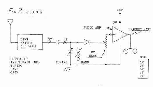
SWITCH 1 - TOP Become familiar with these positions and always return to them on closing the attache case. A. R F DETECTORS (1) R F LISTEN This function consists of an antenna (the input line cord), the INPUT PAIR selector which selects one out of the five input wires to serve as the antenna, a DC blocking/RF bypass capacitor, a seven position BAND selector and associated TUNING capacitor, a detector diode, an RF SENSITIVITY potentiometer, the audlo amplifier and RMS/RF meter MI. Incoming RF is applied to the RF bypass capacitor through the RF position of the INPUT PAIR selector switch. The TUNING and BAND controls further enhance or attenuate the RF signal which is then detected by a diode (lN82 preferred). The resultant signal is applied to the RF SENSITIVITY control. This control is at its maximum output when fully counterclockwise or in the OFF position (view it as an attenuator rather than a gain control). The detected signal is then applied to the audio amplifier. Output of the amplifier may be viewed on the RMS meter M1 or listened to through the headset. The 1080D is designed for use with the special 2,000 ohm headset supplied. Do not use low impedance headsets. The driver element of the headset may be used with the ear hook and adjusted for use on either ear or with the gray stethoscope tube. If the stethoscope tube is used (preferred) it is worn with the tube under the chin with the sound output holes facing slightly forward (30 degrees). FIG 2 shows the BSP for the RF LISTEN mode. A summary of the switch positions appears in the small block to the right of the figure. ALL OTHER SWITCHES REMAIN IN THE BSP. To listen to a demodulated RF signal, insert the input cord into the six pin jack on the left side of the analyzer, insert the headset supplied into the HEADSET (2K) jack, place switch 9 in middle or LV ONLY position and adjust the GAIN control clockwise to a comfortable level. with the BAND switch on I position 1 (the BSP), rotate the TUNING capacitor i approximately 180 degrees. Repeat this tuning procedure on bands 2 through 7. After this test return the switches to the BSP. 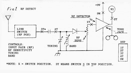
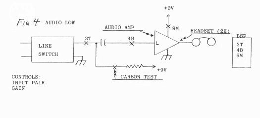
The RF Meter function is identical to the RF Listen function up to the output of the RF SENSITIVITY control. At this point, the signal is routed to the RF Detect circuitry instead of the audio amplifier. The output of the RF Detector is applied to Meter M1. A portion of the signal reaching M1 is returned to a tone generator circuit which produces a tone whose pitch is proportional to the signal strength. This tone is monitored via the jack located to the right of switch 1. FIGURE 1 shows the BSPs for the RF Detect mode. A summary of the BSPs appears in the small block adjacent to the figure. ALL OTHER SWITCHES REMAIN IN THE BSP. To detect incoming RF, insert the input cord into the six pin jack on the left side of the analyzer, insert the headset supplied into the tone jack located to the right of switch 1, turn switch 9 to the middle or LV ONLY position and turn on the RF detector by rotating the RF SENSITIVITY control slightly clockwise (until a click is heard). Rotate the TUNING control 180 degrees while observing M1. Repeat the tuning procedure on bands 2 through 7. Detected RF will cause an immediate increase in the reading of M1 as well as the pitch of the tone heard in the headset. If an excessive amount of RF is present i.e. the meter remains beyond full scale, lower the sensitivity by rotating the RF SENSITIVITY control slowly clockwise. Remember, this control should be viewed as an attenuator i.e. as the control is rotated clockwise the signal level is decreased. After this test, return the switches to the BSP. B. AUDIO AMPLIFIER The audio function consists of the INPUT PAIR selector (line switch), a DC blocking/audio bypass capacitor, a high gain-low noise audio amplifier with high and low input impedance and level, meter Ml and the HEADSET output. An excitation voltage is available at the input side of the blocking capacitor for activating external circuits or a carbon microphone. The input signal may be applied to any of the five color-coded input lines. A color-code to switch position conversion chart is located to the left of the LINE PAIR switch. The LINE PAIR switch connects one of the input lines to chassis ground and the other to the blocking capacitor. with switch 4 in the middle or AUDIO HIGH position the signal is applied to the high impedance (lOOK) input of the amplifier. with switch 4 in the bottom or AUDIO LOW position the signal is applied to the medium impedance (5K) input of the amplifier. The output of the audio amplifier is applied to both the HEADSET jack and MI. FIGURE 3 and FIGURE 4 show the switching positions for the audio high and low functions. A summary of the BSPs are in the blocks adjacent to these figures. ALL OTHER SWITCHES REMAIN IN THE BSP. 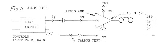
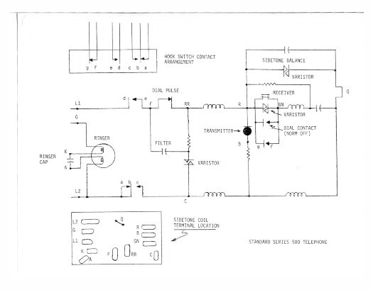
C. TONE GENERATOR (AND CAPACITY MEASUREMENTS) The tone generator and capacity measuring functions are made up of the LINE PAIR selector, a DC blocking capacitor, the audio amplifier, an audio oscillator and meters Ml and M2. The tone oscillator generates a saw-tooth wave whose frequency is adjustable from 20 PPS to 5K PPS. The rapid decay of the saw tooth waves generates usable harmonics to well beyond 25K PPS. The same switch positions are used when measuring capacity and the TONE-FREQ control is set fully clockwise to the CAP position. FIGURE 5 shows the switch procedure for the TONE GENERATOR mode. Note that the headset is not used during this test. To generate a tone, rotate the TONE-FREQ control slightly clockwise until it clicks on. Rotate the GAIN control clockwise to one-half its range. Connect two test clips to an active telephone line and set the LINE PAIR switch to the appropriate position. Voltmeter M2 (center) indicates the telephone line voltage. IF THE VOLTMETER DOES NOT INDICATE, REVERSE THE TEST LEADS. While observing the meter, rotate the TONE-FREQ control slowly clockwise towards maximum. The complete sweep should take 30 to 45 seconds. Any abrupt dip on the voltmeter would indicate a tone activated device. Rock the TONE-FREQ back and forth around any dip point to activate the device. The analyzer contains protective circuits which prevent damage to the tone generator or audio amplifier should an incoming ring occur on the line under test. Capacity is measured by placing the TONE-FREQ control at maximum pitch (fully clockwise) and setting M1 at 100 (full scale) by adjusting the GAIN control. Again, the headset is not used. Addition of capacitance across the test line will cause a decrease in the reading of M1. Make test readings using a .01, .1 and 1.0 MFD capacitors. Place the readings obtained in the small chart adjacent to FIGURE 5. 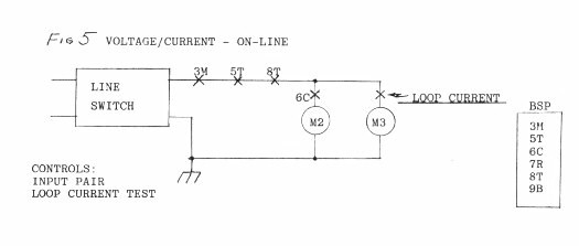 (1) RF/RMS Meter M1 (Left) M1 indicates several functions. The first is relative RF signal strength as detected by the RF Detect circuit. The second is to indicate RMS (AC) signals from the audio amplifier, therefore, M1 will indicate the relative output level of the audio amplifier or (shunt) capacitance. (2) VOLTMETER M2 (Center) The voltmeter indicates either on-line DC or voltages Generated within the analyzer itself. M2 has a sensitivity of 1,000 ohms per volt. This means that a reading of 10 volts on the X10 scale (100 volts) presents a load of 10,000 ohms plus 300,000 ohms (the voltage divider resistance) to the line. The same holds true for the X100 position except that 3 Megohms is added to the basic meter resistance. FIGURE 6 shows the switching procedure for on-line measurement of DC voltages. A summary of switch positions appears in the block to the right of the figure. 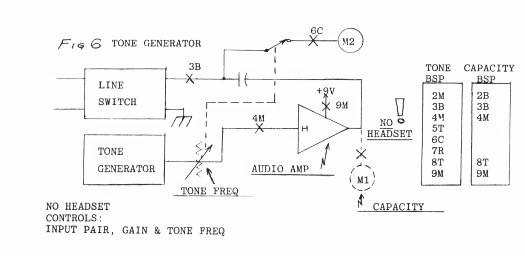 M3 is used to indicate current drawn by a load resistance during tests where the internal high voltage supply is used. It also indicates loop current on an active telephone line. The sensitivity of M3 is selected by Switch 7 which provides ranges of 0-500 uA, 0-5 mA and 0-50 mA. With the loop current switch depressed the full scale sensitivity of M3 is 100 mA. Both the voltmeter and current meter switches are spring-return in the Xl position to prevent accidental damage to the meter movement. 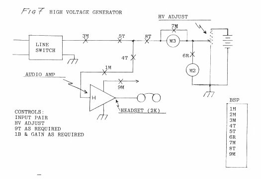 The high voltage section consists of two (2) 500 volt photoflash batteries wired in series for an output of 1,000 volts DC. Whenever Switch 9 is in the HV & LV position (top) the output of the high voltage batteries is applied to the HV ADJUST potentiometer. Switch 9 is spring return from the HV & LV position to the LV ONLY position to prevent unnecessary current drain from the HV batteries and to provide operator safety should accidental contact be made to the high voltage. FIGURE 7 shows the BSP for generating HV. To generate HV hold Switch 9 in the HV & LV position and rotate the HV ADJUST control to the desired voltage. Should it become necessary to listen for audio on the line under test, pull Switch 1 to the spring loaded bottom position (AUDIO MOMENTARY) and adjust the GAIN as required. The spring loaded position of Switch 1 prevents damage to the audio amplifier when pulsing the HV line. F. PULSE GENERATOR The pulse generator circuit is basically the same as the HV circuit with the exception that when one of the two pulse buttons is depressed a capacitor or capacitor and resistance (HOLD) is placed in series with the HV output. with the HOLD Switch in the BSP the output voltage, when one of the two pulse buttons is depressed, will go from the preset HV output to 500 or 1,000 volts beyond that voltage and then to ZERO. with the HOLD Switch in the on or up position the output will go from the preset HV output to 500 or 1,000 volts beyond that voltage and then back to the preset voltage. FIGURE 8 shows the BSP for the HV PULSE function. 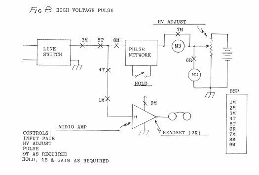 Switch 8 places either a short, 500 ohms or 50,000 ohms in series with the output line. The purpose of these resistors is to provide an increased audio level when looking into high impedance lines or as a current limiting device when pulsing into low impedance loads. H. CURRENT SENSING ALARM The current sensing alarm consists of a pulse amplifier, an SCR and an audible alarm. The small switch to the right or the LEVEL SET control performs a dual function. Shifting the switch to the upward position turns the current sensing alarm on. After the circuit has been triggered, it may be reset by throwing the switch to RESET and back to the up position. The current sensing alarm is turned off by leaving the switch in the RESET position. I. BATTERY TESTS (Place all switches in the BSP.) (1) LV BATTERY TEST All circuits requiring low voltage are powered by two standard 9 volt batteries (alkaline preferred). To test the batteries under load, turn on the audio amplifier by rotating the GAIN control one-quarter of a turn clockwise, place Switch 9 in the LV ONLY position and press the LV BAT TEST button. A reading of from 8 to 10 volts is satisfactory for alkaline batteries while a reading between 7 and 9 volts is acceptable for mercury batteries. (2) HV BATTERY TEST The high voltage section is powered by two 500 volt photoflash batteries wired in series for a total output of 1,000 volts. See section 1. under "NEW BATTERIES" for the examination procedure of new high voltage batteries. Before starting the HV test make sure all switches are in the BSP. Rotate the HV ADJUST control fully clockwise. Momentarily push Switch 9 up to the spring loaded LV & HV position (top). Observe the reading on M2. A reading of 800 volts or above indicates satisfactory battery condition. Release Switch 9 and return it and all other switches and controls to the BSP. III. TELEPHONE TESTING When the 1080D was first developed in 1968 there were a limited number of types of telephones in use and writing a test procedure for each was a relatively easy task. Now that the telephone industry has been "deregulated" and AT&T "broken up", the technician is faced with tens or even hundreds of different types of telephones and telephone systems. The following test procedures will cover two standard telephones, one rotary and the other multiline touch. These procedures give an example of the logic used to test each type of telephone. Once the logic is understood it is possible to expand it to other telephones and telephone systems. SERIES 500 TELEPHONE (ROTARY) A. ON-LINE TESTS Before attempting ANY on-line it is wise to thoroughly study the schematic (shown later in this manual) of the Series 500 telephone and obtain as much technical information as possible about the system being examined. Throughout the U S the telephone lines between the substation or central and the telephone unit carry approximately 48 volts DC. When the handset is lifted from the cradle, this voltage drops to between 4 and 12 volts depending on how the carbon granules are displaced in the mouthpiece. Before proceeding further it is necessary to determine the "auto disconnect" or system reset time. This is the duration between the time the handset is lifted and the system senses that no dial information has been inserted. When the auto reset time is reached a loud click will be heard usually followed by an alert message or tone. Normally this time is on the order of 20 to 40 seconds. Make a note of the time for future use. Following this test, remove the cover from the instrument and tape the hookswitch in the down position. Loosen the two dial mechanism retaining screws (one on each side) and lift off the dial mechanism and place it towards the right side of the telephone. Bear in mind when making a thorough visual inspection of the instrument that telephones of the same type will be like peas in a pod. Whenever possible, have an identical model placed next to the telephone under inspection to serve as a visual comparison. Pay particular attention to the sidetone network. Examine the mouthpiece for the presence of a drop-in transmitter and the earpiece for external devices. Note the crimp marks on the earpiece and mouthpiece. Pull the wires connecting the earpiece to the handset cord back and forth through the passage way to make sure there is nothing within the handset itself. Examine the cable connectors and terminal block connecting the telephone to the system. Make sure that all parts that are normally riveted to the frame are indeed fastened in that manner. Screw mounted components are immediately suspect. Look carefully at the hook-switch contacts to make sure they have not been bent or deformed and that there is nothing between them. A magnifying glass is useful for this inspection. Obviously, any devices (resistors, capacitors, black-boxes, microphones, batteries, etc.) found in the telephone that are not part of the system are immediately suspect. (1) RF Lay the five line cable from the analyzer across the telephone instrument and twist the handset cord around it once or twice. The cable is acting as an antenna so do not connect any of the clips. position the analyzer controls for the RF DETECT mode (FIGURE 1). Rotate the TUNING control 180 degrees while observing M1. Repeat this procedure on bands 2 through 7. If, at any time on any band, the meter reads in excess of 100, switch to the RF LISTEN mode to determine the source of the signal. If the meter reads beyond 100 on all bands and no detected signal can be heard the possibility of RF flooding exists. ( 2 ) AUDIO The following tests apply to a standard Series 500 telephone and serve as a guide for expansion into other telephones. Connect the five line input cable to the sidetone network using the following color codes:
RED TO R Position the controls for the AUDIO HIGH mode (FIGURE 3). With the hookswitch still taped down, examine pair 1,2 and pair 3,4 for audio. NO audio should be heard on 1,2 and normal telephone line noise (less any room audio) should be heard on 3,4. Reset the control for 1,2 and press the CARBON TEST button. Room audio should be recovered. It may be necessary to reduce the GAIN or move Switch 4 to the bottom position during this test. (3) VOLTAGE Position switches for VOLTAGE measurement (FIGURE 5). With the input selector on 3,4 a reading of approximately 48 volts (DC) should be obtained on M2. If the meter reads backwards or not at all, interchange the position of the black/white and red/green wires. When the hookswitch is raised, the reading will drop to between 4 and 12 volts. This low voltage reading will also occur on 1,2. For a closer examination of the lower voltage press Switch 6 to the spring loaded Xl position. (4) CURRENT with the controls still set for VOLTAGE measurement and the input selector on 3,4 press the LOOP CURRENT switch located directly below the ALARM Sonalert. Allow one or two seconds for the current to stabilize and note the reading on M3. Should the reading exceed full scale move Switch 8 to the R (X100) position. As in the case of voltage measurements, this reading will generally be useful only if two or more telephones on the same system are tested. RULE: If the voltage is lower than normal, a parallel device is suspected and if the current is lower than normal, a series device is suspected. (5) TONE ANALYSIS with the headset removed, position the switches as in FIGURE 6T. Place the input selector on 3,4 and rotate the GAIN and TONE-FREQ controls one-half turn clockwise. Lift the hookswitch and listen to the telephone earpiece. A tone should be heard superimposed on the dial tone. Tape the hookswitch back in the down position. Rotate the TONE-FREQ control counterclockwise until it rests against its OFF stop (but not turned OFF). with the controls properly set the reading on M2 should be the same as in (3). While observing M2, slowly rotate the TONE-FREQ control clockwise towards maximum. The complete sweep should take 45 to 60 seconds. Any dip in voltage indicates the possibility of a tone activated device. To trigger a tone device, rockcc, the TONE-FREQ control back and forth around any dip. B. OFF-LINE TESTS With the input cable still connected to the telephone, dlsconnect the telephone from the llne. (1) RF If the telephone contained a battery operated device, it would have been uncovered during the physical search. Therefore, no off-line RF test is necessary. (2) AUDIO Set the switches for the AUDIO HIGH mode (FIGURE 3). a. AUDIO FROM RECEIVER (EARPIECE)
1. Press the hookswitch down and listen for
audio in all INPUT PAIR positions. NO audio should be recovered. b. AUDIO FROM TRANSMITTER (MOUTHPIECE)
1. Press the hookswitch down and listen for audio in all INPUT PAIR positions. NO audio should be recovered. c. AUDIO FROM RINGER For this test it will be assumed that terminal G is shorted to terminal L1 on the sidetone network OR the ringer connects directly to L1. Press the hookswitch and listen for recovered audio in LINE PAIR position 3,4. NO appreciable amount of audio, even with the GAIN turned to maximum, should be recovered while talking directly at the ringer in a loud voice. (3) a. VOLTAGE CAUTION !! THE HIGH VOLTAGE SECTION IS USED FOR THE FOLLOWING TESTS. USE EXTREME CAUTION WHEN HANDLING THE TEST LEADS. FOR SAFETY, ALWAYS WORK WITH ONE HAND ONLY AND WITH THE OTHER HAND HELD IN A CLENCHED FIST IN A REAR POCKET. For voltage tests set the switches for the HIGH VOLTAGE mode (FIGURE 7).
1. Tape down the hookswitch. CAUTION !! DURING THE TEST OUTLINE IN STEP 11 THE METAL FRAME OF THE TELEPHONE WILL BE AT THE HIGH VOLTAGE POTENTIAL. DO NOT TOUCH THE TELEPHONE! 12. Place Switch 5 in the MINUS position and repeat steps 3 through 11. When complete, return Switch 9 to the OFF position.
b . CURRENT
1. position the INPUT PAIR selector on 1,3. with the hookswitch up, push Switch 9 to the top spring loaded LV & HV position and rotate the HV ADJUST control clockwise for a reading of 250 volts on M2. Release Switch 9. (4) PULSE ANALYSIS The purpose of this test is to detect modifications made to the hookswitch which would make the telephone useful for eavesdropping while the handset is in the hung up (on cradle) position. The pulse circuit can detect capacitances as small as 10 Pf and current as low as 2 uA.
1. Tape the hookswitch in the down position. (5) CAPACITY ANALYSIS Set the controls for the CAPACITANCE TEST mode (FIGURE 6C). Make sure the ringer capacitor is still disconnected. with the analyzer headset removed and the INPUT PAIR switch on the unmarked position (9 O'Clock) rotate the TONE-FREQ control to CAP. Adjust the GAIN control for a reading of 100 on M1.
a. Press the hookswitch downward and measure the capacity on positions 1,3; 2,4; 1,5 and 2,5. All of these settings should indicate ZERO capacitance i.e. M1 remains at full scale (100).
SERIES 2565 TELEPHONE (TOUCH) The following tests apply to a standard 2565 multi-line telephone and serve as a guide for other multi-line telephones. The general method of physical inspection are as outlined in section III.A. with the exception that particular attention should be paid to the push button line selector matrix. If it is held in place by screws, remove the screws and check underneath. Make sure it has not been rewired or if there are any mismatched wire color combinations. Check inside the shell of both the plug and connector. Look for rewire or devices.
(1) RF
ON THE SIDETONE NETWORK RED TO RPosition the switches for AUDIO HIGH (FIGURE 3). With the hookswitch down, examine pairs 1,2 and 4,5 for audio. NO audio should be recovered in position 1,2 and normal telephone line noise should be heard on 4,5. Turn the LINE PAIR selector to 1,2 and press the CARBON TEST button; audio should be recovered. (3) VOLTAGE Position switches for VOLTAGE (FIGURE 5). With the input selector set on 4,5, a reading of approximately 48 volts will be obtained on M2. If the M2 reads backwards or not at all, interchange the position of the WHITE and BROWN wires. If no reading is obtained after the clips have been interchanged then T1 and R1 is not an active line. Move the clips to T2 and R2, etc. until an active line is located. When the hookswitch is raised, the voltmeter will indicate between 4 and 12 volts. Momentarily press Switch 6 to the left (Xl) for a more detailed reading. Assuming T1 and R1 were a valid pair, remove the RED and GREEN clips from R and B and place them on T2 and R2. Make sure that 1,2 and 4,5 both show 48 volts with the hookswitch down. The voltage readings, assuming both lines come from the same central, should be identical. Leave the test leads connected as they are for the following tests. (4) CURRENT With the controls still set for voltage measurement and the input on 1,2, press the LOOP CURRENT switch and note the current on M3. Make the same test on 4,5. Again, assuming both lines come from the same central, the reading should be identical. After these comparisons have been made move the WHITE and BROWN leads to T3 and R3 and repeat the above VOLTAGE AND CURRENT tests. On completion, move the RED and GREEN clips to T4 and R4 and so on until all active lines have been tested. (5) TONE ANALYSIS With the analyzer headset removed and the input cable completely disconnected, position the switches for the TONE GENERATOR mode (FIGURE 6). Set the input switch on 1,2 and the GAIN and TONE-FREQ one-half turn clockwise. Connect the RED and GREEN wires to T1 and R1. If M2 reads backwards or not at all, reverse the leads. Press the telephone button for the first line and listen to the handset. A tone superimposed on the dial tone should be heard. Lightly press the button for line two to bring all buttons to the up position. Rotate the TONE-FREQ control counterclockwise until it rests against the OFF stop but is not off. Observe M2 while slowly rotating the TONE-FREQ control clockwise. The complete sweep should take 45 to 60 seconds. A dip in the voltage reading on M2 could indicate a tone activated device. Rock the control back and forth around the dip point to activate any device. Repeat the above test on T2/R2 through all other active lines. B. OFF-LINE TESTS (1) RF If the telephone contained a battery operated device, it would have been discovered during the physical search. Therefore, no off-line test is necessary. (2) AUDIO
Set the analyzer for the AUDIO HIGH mode (FIGURE 3).
Connect the RED and GREEN leads to terminals Rand B on the sidetone network and place the input selector on 1,2.
a. AUDIO FROM RECEIVER 1. Press the hookswitch down and listen for recovered while speaking into the handset receiver (earpiece). No audio should be recovered. NOTE: On some of the newer 2565s audio may be recovered during this test. Carefully inspect the hookswitch receiver (earpiece) shunt contacts. If audio exists, inspect terminals R, Band GN for additional wires. AUDIO FROM TRANSMITTER
1. Press the hookswitch downward and listen for recovered audio. NO audio should be recovered while speaking directly into the handset transmitter (mouthpiece). AUDIO FROM RINGER Connect the RED and GREEN leads to RR and RT on the switching matrix. Listen for recovered audio while speaking directly at the ringer. NO audio should be recovered. As mentioned previously, the hookswitch in the 2565 is not in the audio path so tests (3)a., (3)b., (4) and (5) as outlined in section III are not necessary.
LOCATION DEVICE TEST
C. RINGER RESISTOR ~ON-LINE/AUDIO CAPACITOR OFF-LINE/AUDIO, RESISTOR/ VOLTAGE & CURRENT CAPACITOR DIODE D. HOOK-SWITCH RESISTOR ON-LINE/AUDIO CAPACITOR OFF-LINE/AUDIO, RESISTOR/ VOLTAGE, CURRENT & CAPACITOR PULSE DIODE, STANDARD REWIRE DIODE, ZENER DIODE, MULTILAYER S C R ~ TRIAC NEON E, F & EARPIECE CAPACITOR ON-LINE/AUDIO (RECEIVER) 3 & 4 WIRE BYPASS OFF-LINE AUDIO & PULSE G. MOUTHPIECE DROP-IN ~ON-LINE/R F (TRANSMITTER) SERIES PARASITE J 'OFF-LINE/AUDIO, 3 & 4 WIRE BYPASS VOLTAGE & CURRENT |
3/09