![]()
![]()
|
CAUTION....DO NOT CONNECT THIS UNIT TO ANY LINE CONTAINING AC OR DC VOLTAGES! THE 1080CT GENERATES A HIGH VOLTAGE OUTPUT. BE CAREFUL WHEN HANDLING THE TEST LEADS.
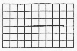
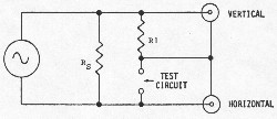 When not connected to a test object there is no current flow through R1 and the vertical input shows no voltage. The horizontal input, however, sees the full sine-wave potential across RS causing a straight horizontal line to appear as shown in FIG 2. NOTE: For oscilloscope graticules six divisions high, adjust the length of the horizontal line so it is three divisions' each side of the center vertical line; if eight divisions high, adjust for four divisions on each side.
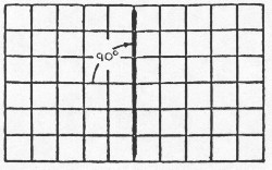
 The vertical input sees the drop across R1 when the device under test is a short or very low resistance. A direct short shunts the horizontal input and creates a vertical line. NOTE: Adjust the vertical input so the line touches the top and bottom lines of the graticule and is centered.
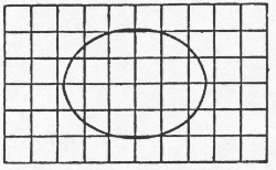
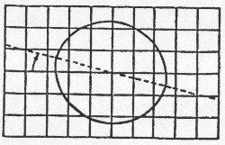
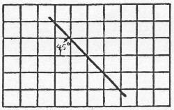 As noted in the preceding examples, when the test circuit is purely resistive, the resulting pattern is a straight line. This is because the sine-wave applied to the horizontal input is exactly 180 degrees out of phase with the sine-wave applied to the vertical input. When the test circuit is reactive, the vertical and horizontal input sine-wave will no longer be 180 degrees out of phase and the pattern will no longer be a straight line. Depending on the amount of reactance (capacitive, inductive or both) the pattern will take on a circular or elliptical shape as shown in FIG 5. Any resistive component in the test circuit will rotate the circular or elliptical pattern clockwise from horizontal. See FIG 6.
 The sensitivity of the 1080CT depends on the value of R1. The unit detects resistance as high as 12 Megohms, however, with a high value of R1 the low end sensitivity (the ability to differentiate between shorts and very low resistance) decreases. The addition of switched R2 (1,000 ohms - FIG 7) retains high end sensitivity and provides increased low end sensitivity. R2 is connected in parallel with R1 by pressing the HI SENS (HIgh SENSitivity) switch. This switch has a momentary and locked position. It is possible to detect resistance as low as 5 ohms with R2 in parallel with R1.

In theory, individual laws of electronics decide the patterns. As one observes the actual patterns, note that they are not necessarily identical. This is because several laws of electronics are involved in deciding each pattern. The theoretical pattern for an open circuit or very high resistance is a straight horizontal line while a short causes a straight vertical line. In reality, when testing capacitors the pattern tilts slightly from leakage resistance. As mentioned earlier, the 1080CT detects resistance between 5 ohms and 12 Megohms. It is possible to detect capacitances as low as 50 pF and as high as 20 uF. Figures 7 and 8 show typical patterns for telephone circuits. Do not become dependent upon "picture recognition." Learn to understand why and how the patterns appear as they do. The 1080CT requires a dual trace oscilloscope. The cables supplied connect the horizontal (H) and vertical (V) outputs of the 1080CT to the horizontal and vertical inputs on the oscilloscope. Insert the test leads into the matching color TEST jacks. BLACK is test circuit ground. This is important when testing circuits that share a common ground with the oscilloscope. Test instruments, such as a telephone/wire analyzer or multimeter, are connected to the 1080CT through the auxiliary (AUX) jacks. This time saver allows switching these accessories into and out of the circuit. OPERATION: Configure the oscilloscope for X-Y operation. Turn on the 1080CT and adjust the oscilloscope so the straight horizontal line covers three quarters of the screen and is centered on the graticule. Short the test leads together and adjust the oscilloscope so the now vertical line covers the same number of squares. Connect the test leads to a 100K ohm resistor and note the pattern rotates to 45 degrees, i.e., the internal resistor R2 is the same value as the external resistor. Connect the test leads to a 1,500 pF (.0015 uF) capacitor. The reactance of this capacitor at 1,000 Hz (the frequency of the oscillator in the 1080CT) is 100K ohms and an absolutely circular pattern appears. If the frequency were to change (which it can't) the value of the capacitor would also have to change. The capacitive/inductive reactance chart provided with this manual proves useful here. With the INT/CONT HI SENS switch pushed upwards or pulled downward (locked) a .15 uF capacitor equals 1,000 ohms (the value of R2). The 1080CT analyzes telephone instruments only when they are disconnected from the telephone line. Connect the test leads to the telephone and lift the handset from the cradle. A vertical or near vertical line should occur indicating a near short (as compared to 100K). Pull back the multiplier switch. The pattern will tilt. Blow or whistle into the mouthpiece and note the variations in the position of the line. If possible, remove and physically inspect the mouthpiece element. Set it aside. When testing telephones, keep in mind that for any given type they are like peas in a pod. The pattern for all ringers will be the same; the patterns for all networks will be the same; the pattern for all earpiece elements will be the same; etc. If necessary, expand the shape of the pattern by using the vertical and horizontal volts/division controls. Make a chart to record the oscilloscope control settings for each test. Multiple copies made of the blank chart at the end of this manual will serve nicely. Telephone, AC power and intercom lines can be tested PROVIDED THEY DO NOT CONTAIN ANY VOLTAGE. Connect the 1080CT to the line and adjust the oscilloscope for a workable pattern. Note the settings. Line pairs are mostly capacitive and inductive and usually do not show much pure resistance. Knowing in advance what to expect for a given length and type of wire is helpful. Connect the BLACK lead to the ground side, if one exists. The auxiliary (AUX) terminals are for connecting an external meter or telephone/wire analyzer to the component or circuit under test. The AUX/TEST switch selects either the external accessory or the 1080CT. Two 9 volt Alkaline batteries power the 1080CT. Zinc-carbon batteries are not recommended. Replace the batteries when the circular pattern of the test capacitor begins to flatten on either side. To replace the batteries, remove the front panel screw and carefully remove the front panel, replace the batteries and replace the panel and screw. Other test instruments that complement the 1080CT are:
1080D MK II Telephone Analyzer 1080TDR Time Domain Reflectometer
9/15 |
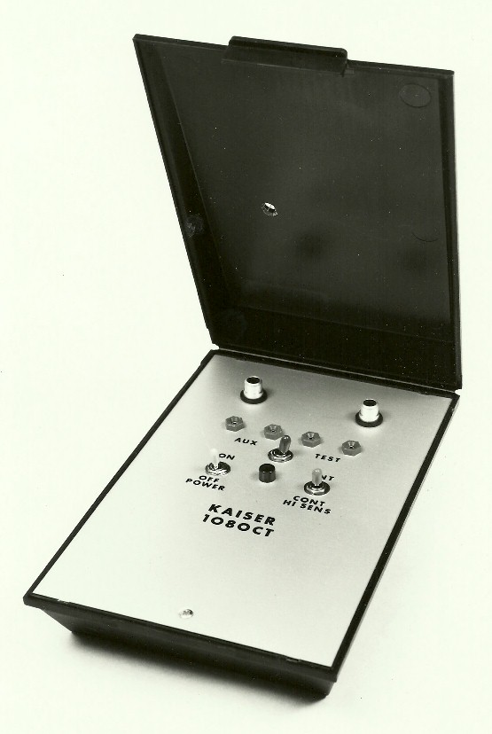 The 1080CT is a battery operated voltage divider/phase shift indicator designed for use with any oscilloscope configured as an X-Y indicator. The unit tests an off-line telephone, a "dry" telephone line and electrical or other line pairs. It also identifies components such as resistors, capacitors, diodes and inductors.